
Application-configured platform
Electronic commutation · very low rotor inertia
Coreless BLDC & Servo Motors
Compact brushless motor platforms combining rapid dynamic response, smooth torque and long service life for speed, torque and position control.
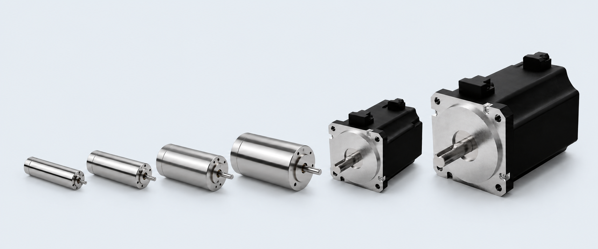
Six diameter platforms
Coreless BLDC & Servo Range
Select the starting diameter around the available envelope, speed, continuous torque and dynamic response. Final winding and stack length are confirmed against the application duty.
Application-configured platform
Application-configured platform
Application-configured platform
Application-configured platform
Application-configured platform
Representative selection data
Performance Envelope by Motor Diameter
Use these values for initial product-family selection. SDT then matches the winding, motor length, feedback and controller to the required operating point, duty cycle and installation conditions.
| Motor diameter | Nominal voltage | Rated power | Typical speed | Continuous torque | Peak torque* | Maximum efficiency | Typical length |
|---|---|---|---|---|---|---|---|
| Ø16 mm | 12–24 VDC | 20–50 W | 15,000–55,000 rpm | 5–25 mNm | 15–75 mNm | 80–90%+ | 30–50 mm |
| Ø22 mm | 12–48 VDC | 30–100+ W | 10,000–50,000 rpm | 20–50 mNm | 60–150 mNm | 85–91% | 35–60 mm |
| Ø26 mm | 12–48 VDC | 30–100 W | 8,000–30,000 rpm | 30–70 mNm | 90–210 mNm | 80–90% | 40–60 mm |
| Ø32 mm | 12–48 VDC | 50–150 W | 8,000–25,000 rpm | 50–120 mNm | 150–360 mNm | 85–92% | 40–70 mm |
| Ø45 mm | 24–48 VDC | 100–400 W | 5,000–15,000 rpm | 0.10–0.40 Nm | 0.3–1.2 Nm | 85–92% | 60–100 mm |
| Ø80 mm | 24–72 VDC | 300 W–1.2 kW | 3,000–10,000 rpm | 0.5–2.5 Nm | 1.5–7.5 Nm | 85–93% | 80–160 mm |
01Use of the values
The table shows a representative family envelope across different windings, motor lengths and thermal designs—not one simultaneous operating point.
02Peak torque
Peak torque is a short-duration capability governed by controller current, winding temperature, cooling and the application duty cycle.
03Final technical release
SDT confirms the continuous and peak operating points for the selected motor, controller and duty before quotation and technical release.
Coreless and slotless motor technical dataReview the representative performance ranges and application-selection information.
Technical PDFRequest Technical Datasheet →Engineering selection criteria
Select by Duty, Control and System Fit
A motor diameter is only the starting point. SDT converts the application duty into a controlled motor, feedback and mechanical configuration, then releases the final performance data for approval.
01
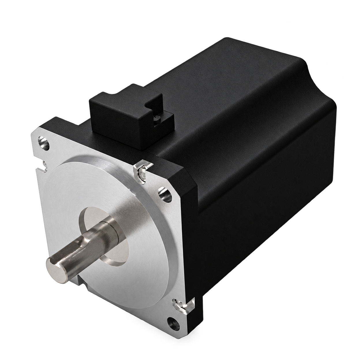
Define the operating point
Confirm supply voltage, target speed, continuous torque, peak torque duration and duty cycle before choosing diameter or winding.
Output: verified speed-torque-duty requirement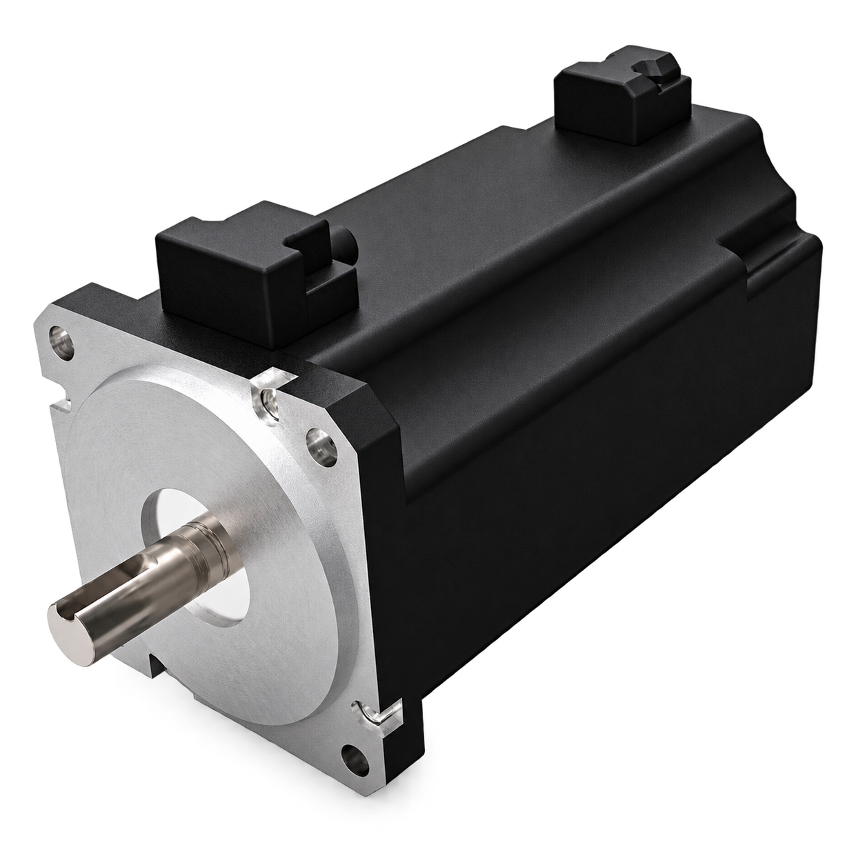
02
Select the control architecture
Choose BLDC commutation for speed and torque control, or encoder feedback for closed-loop speed or position performance.
Output: motor, feedback and controller route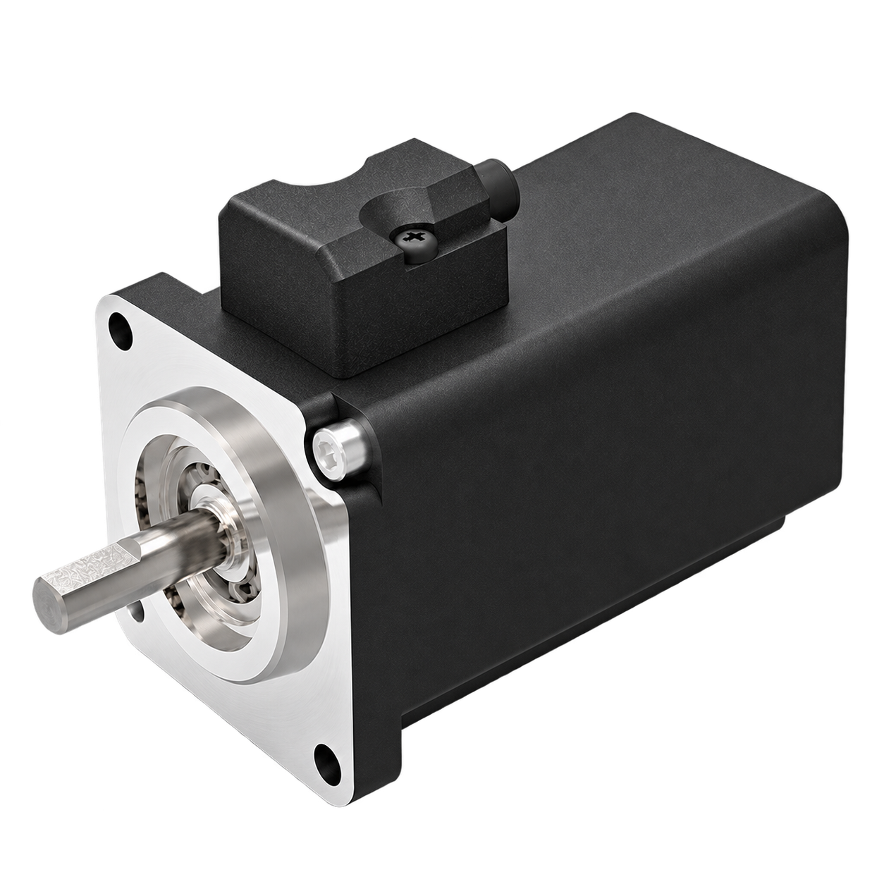
03
Validate the complete assembly
Review thermal margin, shaft loads, brake duty, gearbox ratio, backlash, connectors and installation envelope as one system.
Output: application-approved motor assemblyCoreless brushless advantages
Fast, Smooth and Efficient Motion
The coreless electromagnetic structure reduces moving mass, while electronic commutation removes mechanical brush wear.
No mechanical commutation
Electronic commutation avoids brush wear and supports long operating life.
Very low inertia
The ironless moving structure responds rapidly to acceleration and braking commands.
No cogging
Smooth rotation and low torque ripple support accurate low-speed and servo motion.
Compact power density
High-performance magnetic circuits provide useful output from a compact motor envelope.
High-speed capability
Low rotor mass and brushless commutation support demanding rotational-speed requirements.
System configuration
Winding, feedback, controller, brake and gearbox are matched to the complete duty.
Two control routes
BLDC or Closed-Loop Servo Configuration
Coreless BLDC Motors
Brushless speed and torque operation configured with the required winding, Hall feedback and electronic controller.
Coreless Servo Motors
Encoder-equipped platforms for accurate speed or position control, with brake and gearbox options where required.
Complete Motion Assembly
Motor, feedback, holding brake, gearbox and controller reviewed as one operating system.
Application-specific engineering
Available Customisation
Electrical design
Voltage, winding, speed constant and current matched to the controller and duty.
Feedback & control
Hall sensors, encoders and controller selected for commutation and regulation.
Mechanical interface
Shaft, flange, housing, connector and stack length adapted to the installation.
Brake integration
Fail-safe holding brake configured for vertical or stationary-load axes.
Matched gearbox
Ratio, backlash, efficiency and output loading reviewed with the motor.
Production supply
Validated configurations documented for repeatable OEM production delivery.
Define Your Coreless Motor Requirement
Share the motion profile, envelope, voltage, feedback, brake, gearbox and controller requirements.