Technology overview
Select the Motor, Drive and Mechanical Architecture as One System
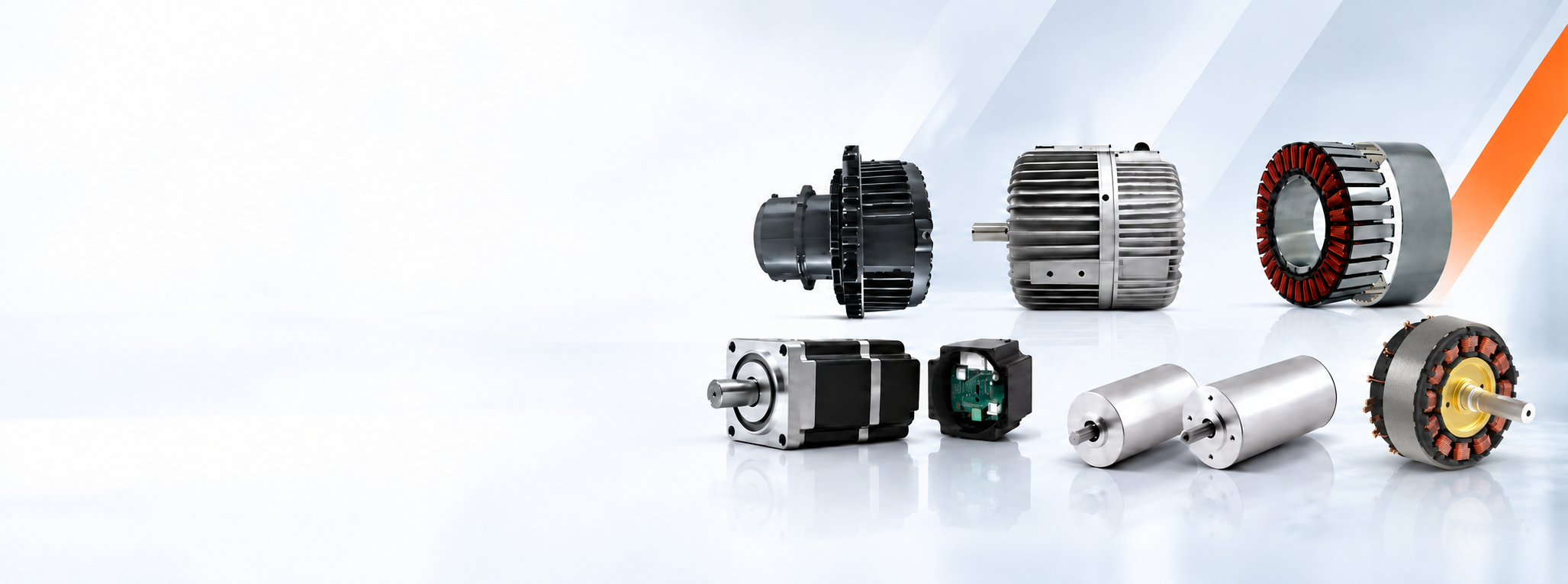
The correct solution starts with the application. Drawing on experience across major electric-machine technologies—including brushless DC, switched reluctance and specialist operating environments—SDT compares speed, torque, duty, supply, control, environment, available space and production requirements before selecting a standard, configured or bespoke route.
Choose by requirement
Seven Ways SDT Can Shape the Motor Solution
Start with the outcome you need—not a predetermined motor type. Open a route to see what it means, where SDT adds value and the most relevant product or engineering pathway.
Application-specific high-speed development capability, subject to complete motor, bearing, thermal and controller validation.
01VARIABLE SPEED · IE3–IE5Variable-Speed & High-Efficiency Motor Systems
Standard, matched & developedView detailsHide details
Variable-Speed & High-Efficiency Motor Systems
Induction, SynRM, PMSM and EC routes selected around the duty, control range and verified efficiency objective. IE3–IE5 is stated only where the applicable motor or power-drive-system standard supports the claim.
Explore More02COPPER-ROTOR INDUCTIONCopper-Rotor Induction Motors
Project selection & developmentView detailsHide details
Copper-Rotor Induction Motors
A project-defined induction-motor route using a cast or fabricated copper rotor where reduced rotor losses, operating efficiency, thermal behaviour and production economics justify the design choice.
Explore More03MOTOR-ONLY · MATCHED VFDAC Motors—with or without a Drive
Standard / configuredView detailsHide details
AC Motors—with or without a Drive
Mains-fed, converter-ready or drive-matched AC motor packages. SDT can supply the motor alone or define the motor, VFD, protection and operating parameters as one application-matched system.
Explore More04EXTERNAL ELECTRONICSBLDC/PMSM Motors without an Integrated Controller
Motor-only & matchedView detailsHide details
BLDC/PMSM Motors without an Integrated Controller
Motor-only brushless platforms for connection to the customer’s or a separately supplied electronic controller. Electronic commutation is always required; Hall, encoder or sensorless feedback is selected with the control strategy.
Explore More05UP TO 100,000 RPMHigh-Speed Brushless Motor Development
Validated by projectView detailsHide details
High-Speed Brushless Motor Development
Application-specific BLDC/PMSM development for speeds up to 100,000 rpm where rotor integrity, bearings, balance, losses, cooling and controller performance are engineered and validated for the defined duty—not a blanket catalogue rating.
Explore More06DIRECT DRIVE · FRAMELESS · TRACTIONDirect-Drive, Frameless & Traction Motors
Configured & bespokeView detailsHide details
Direct-Drive, Frameless & Traction Motors
Integrated rotor-and-stator sets, torque motors, wheel drives and traction machines developed around the equipment structure, torque-speed envelope, cooling, feedback, bus voltage and mechanical interfaces.
Explore More07SRM + DEDICATED DRIVESwitched-Reluctance Motor Systems
Evaluation & developmentView detailsHide details
Switched-Reluctance Motor Systems
Magnet-free motor-and-controller appraisal and development for duties where robustness, wide speed range, temperature capability or rare-earth-free construction can justify the acoustic, torque-ripple and control-engineering work.
Explore MoreAC motor and drive technology
See the Difference Between the Motor, the VFD and the Complete System
An AC motor can operate directly from the mains, be prepared for converter operation, or be supplied with a matched variable-frequency drive. Copper-rotor induction is a separate, project-defined efficiency route inside the motor—not a type of electronic drive.
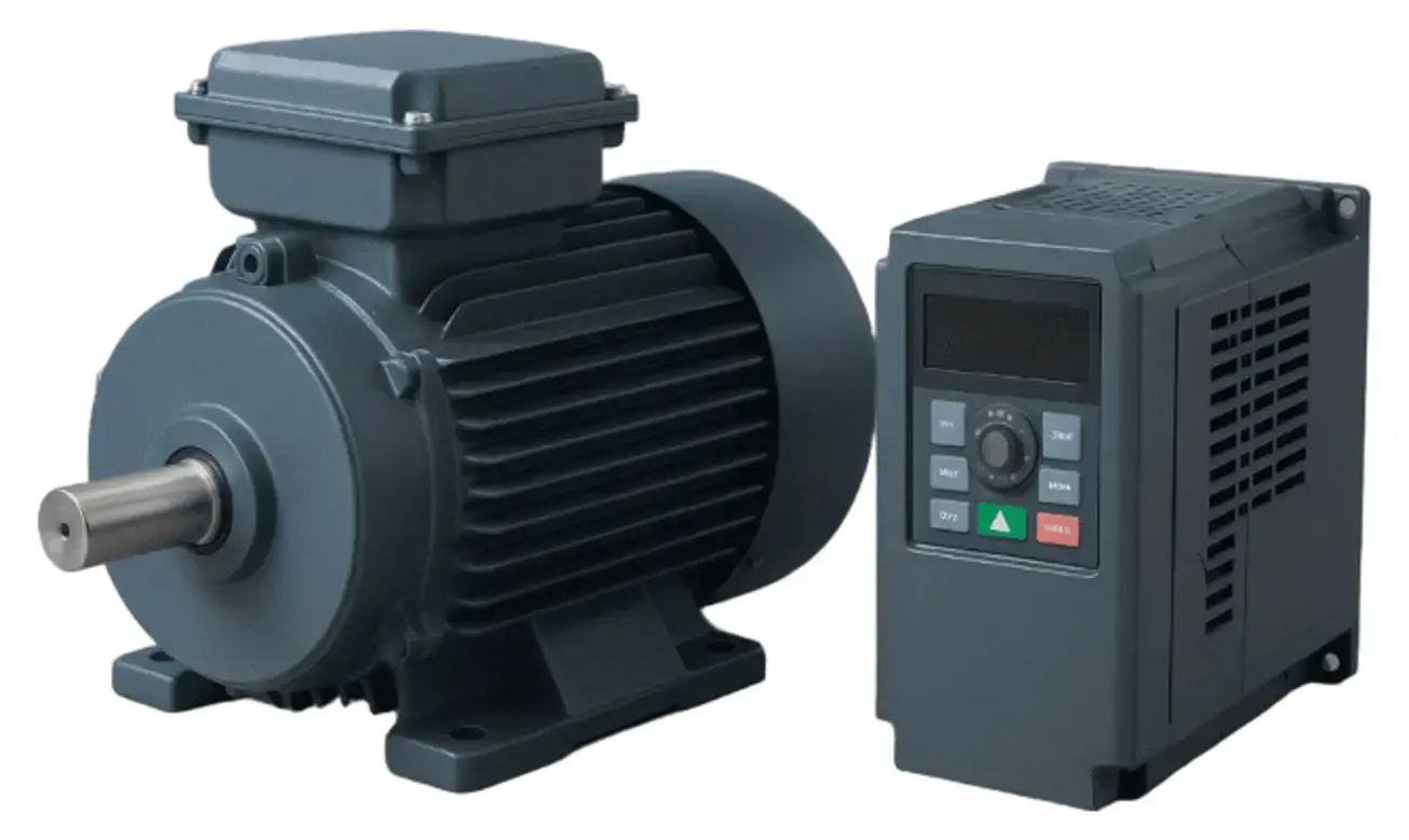 AC induction motor with a separate variable-frequency drive
What a Variable-Frequency Drive Does
A VFD converts the fixed-frequency electrical supply into a controlled output with adjustable frequency and voltage. This allows a compatible AC motor to deliver the speed and torque required by the machine instead of running continuously at one mains-determined speed.
A VFD introduces its own losses, so energy savings are application-dependent. SDT evaluates the complete motor-drive system, operating points and control method rather than making a blanket efficiency claim.
Explore More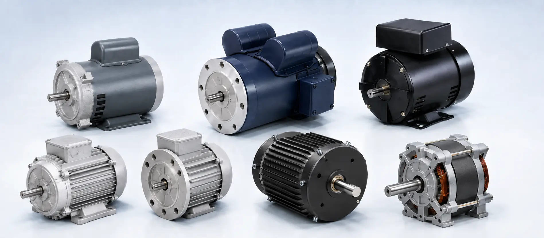
With or Without a Drive
The external motor appearance may be similar, but the winding, insulation, cooling and operating duty must suit the selected supply method.
- Direct-on-line: fixed-speed mains operation
- Converter-ready: motor prepared for the customer’s VFD
- Matched package: motor, VFD, parameters and protection defined together
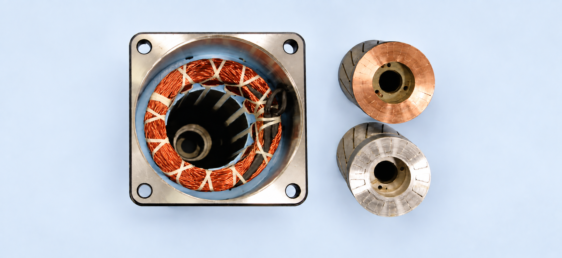
What Changes in a Copper-Rotor Motor?
The motor remains an induction motor and can look identical externally. The difference is inside: copper conductors replace aluminium in the squirrel-cage rotor to reduce rotor resistance and associated I²R losses.
- Potential for lower rotor loss and reduced heat
- Possible efficiency or package-size improvement
- Requires electromagnetic, thermal and manufacturing redesign and validation
Offered as a feasibility and development route—not a standard catalogue claim. Efficiency is confirmed for the final motor under the applicable test standard.
Explore MoreUnderlying motor technologies
The Electromagnetic Technologies Behind the Solution
The selected product route may combine one or more motor technologies with the correct controller, efficiency evidence and mechanical architecture.
AC Induction & PSC
Asynchronous AC motor technologies covering three-phase induction and compact single-phase permanent-split-capacitor platforms. Variable speed is achieved with a suitable inverter and converter-duty motor design.
Pumps, fans, conveyors, process machinery and equipment requiring robust continuous-duty operation.
Permanent-Magnet DC
Brushed DC technology with permanent-magnet excitation, straightforward voltage or PWM speed control and useful starting torque.
Battery-powered equipment, actuators, pumps, mobile machinery and cost-conscious geared motion.
Brushless DC & Permanent-Magnet Synchronous
Electronically commutated permanent-magnet machines. BLDC and PMSM describe related motor-and-control approaches; SPM and IPM describe where the rotor magnets are positioned, not separate product families.
Efficient variable-speed equipment, high-cycle machinery, pumps, compressors, automation and compact high-performance motion.
Synchronous Reluctance
Magnet-free synchronous technology using rotor saliency to produce torque. It is normally operated with a matched variable-speed drive and appropriate control parameters.
High-efficiency variable-speed pumps, fans, compressors, conveyors and industrial process equipment.
Switched Reluctance
Magnet-free, doubly salient motor technology requiring a dedicated electronic controller and position-dependent phase switching. Torque ripple, acoustics and control strategy must be engineered together.
Wide-speed, high-speed, high-temperature, robust or rare-earth-free duties where its system-level advantages justify development.
Stepper Motor Technologies
Permanent-magnet, variable-reluctance or hybrid incremental motors operated from a matched driver. Closed-loop feedback may be added where position assurance or higher dynamic performance is required.
Indexing, feeding, dosing, positioning and repeatable low- to medium-speed machine functions.
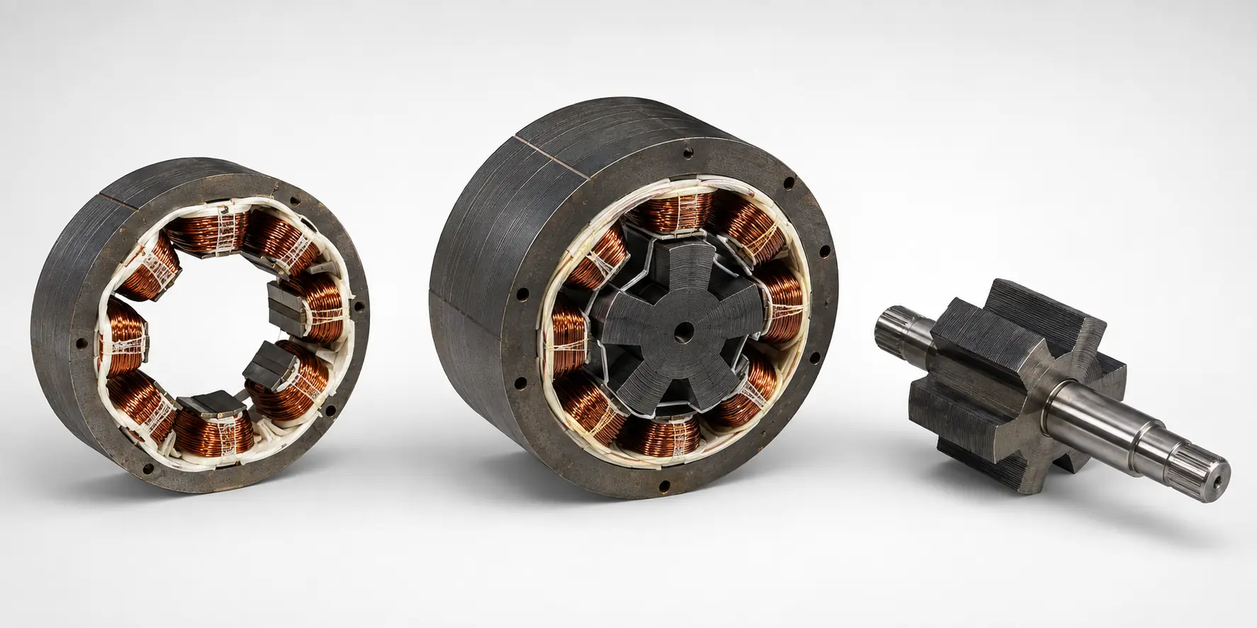
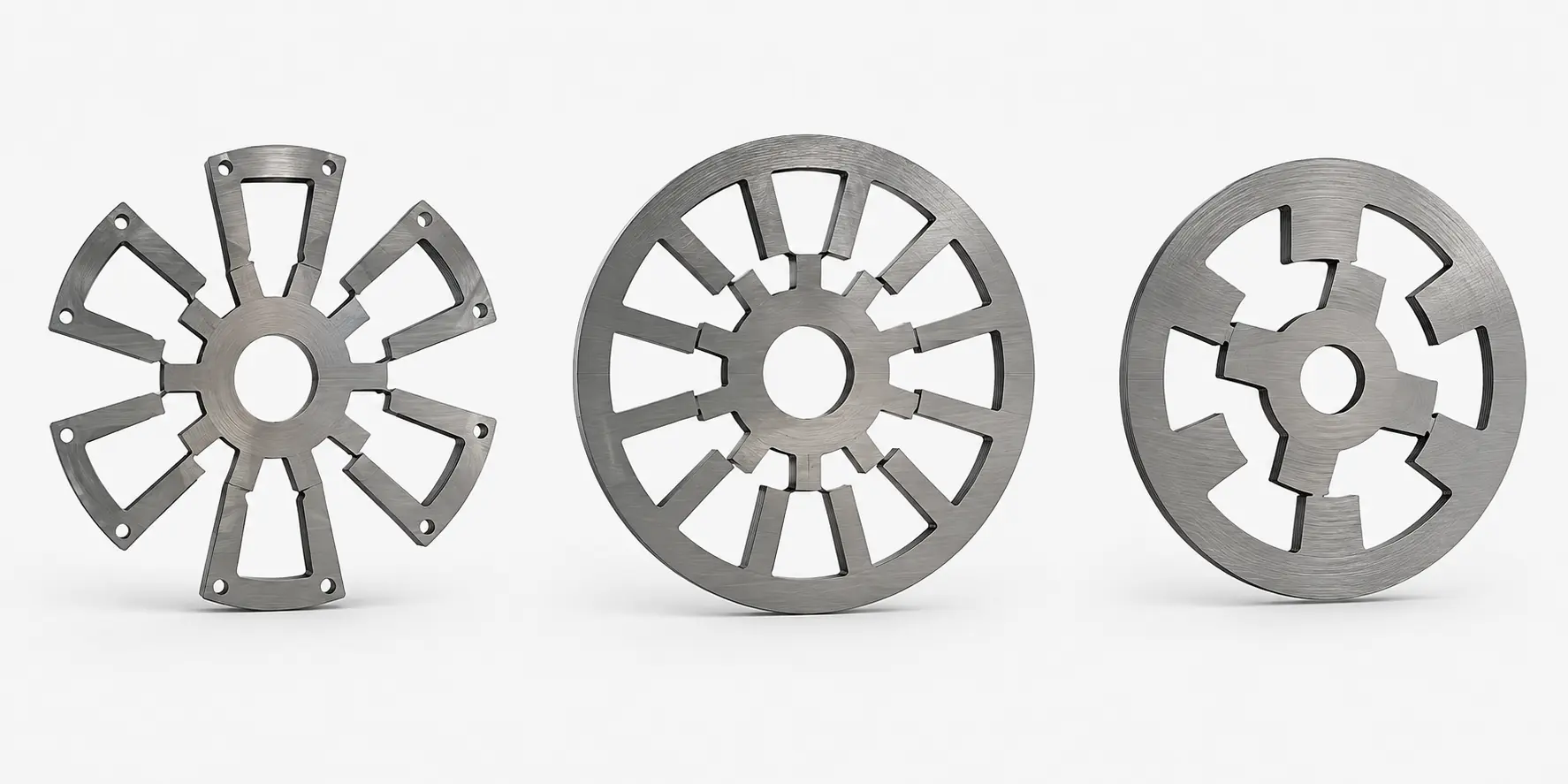
Switched-Reluctance Motor & Controller Development
SDT evaluates the complete magnet-free motor-and-controller system around the required speed range, torque, thermal duty, acoustic limits and equipment interface.
- Electromagnetic and mechanical concept development
- Dedicated controller and position-dependent phase control
- Prototype correlation and production-readiness support
The images show representative custom development work—not a released standard catalogue range.
Explore MoreMotor technology
How electromagnetic torque is produced: induction, permanent-magnet DC, BLDC/PMSM, reluctance or stepper.
Speed & control
Fixed speed or variable speed describes operation; it does not define the underlying motor technology.
Integration architecture
An external drive, adjacent controller or integrated controller describes how the motor and electronics are packaged.
Efficiency evidence
IE3, IE4 and IE5 are efficiency classifications applied under the relevant motor or power-drive-system standard.
Brushless product architecture
One Brushless Technology Family. Three Ways to Integrate It.
Within SDT’s portfolio, PMSM is part of the wider brushless permanent-magnet offering—not a disconnected product family. The required speed, torque, control and equipment interface determine the most suitable construction.
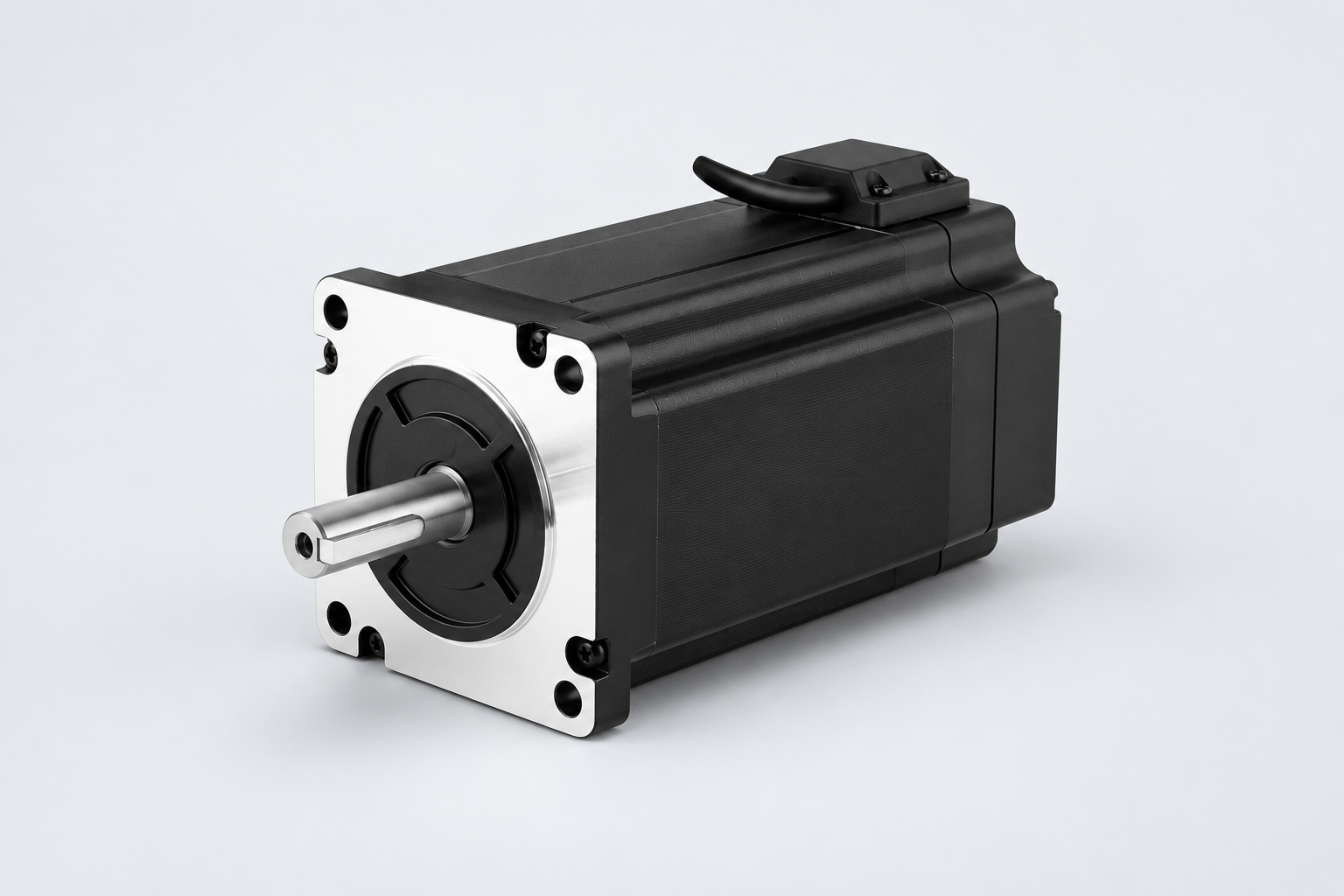
BLDC / PMSM Motor
A brushless motor platform supplied for connection to the customer’s controller, with winding, feedback, shaft and mounting selected around the application.
Explore More →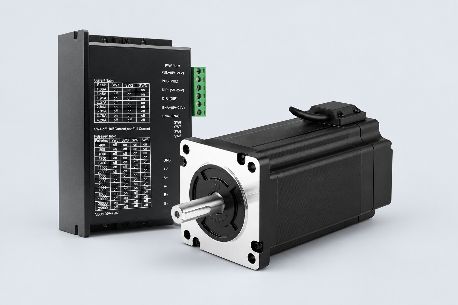
Motor + Separate Controller
A matched external controller retains coordinated motor performance while improving electronics cooling, service access and packaging flexibility.
Explore More →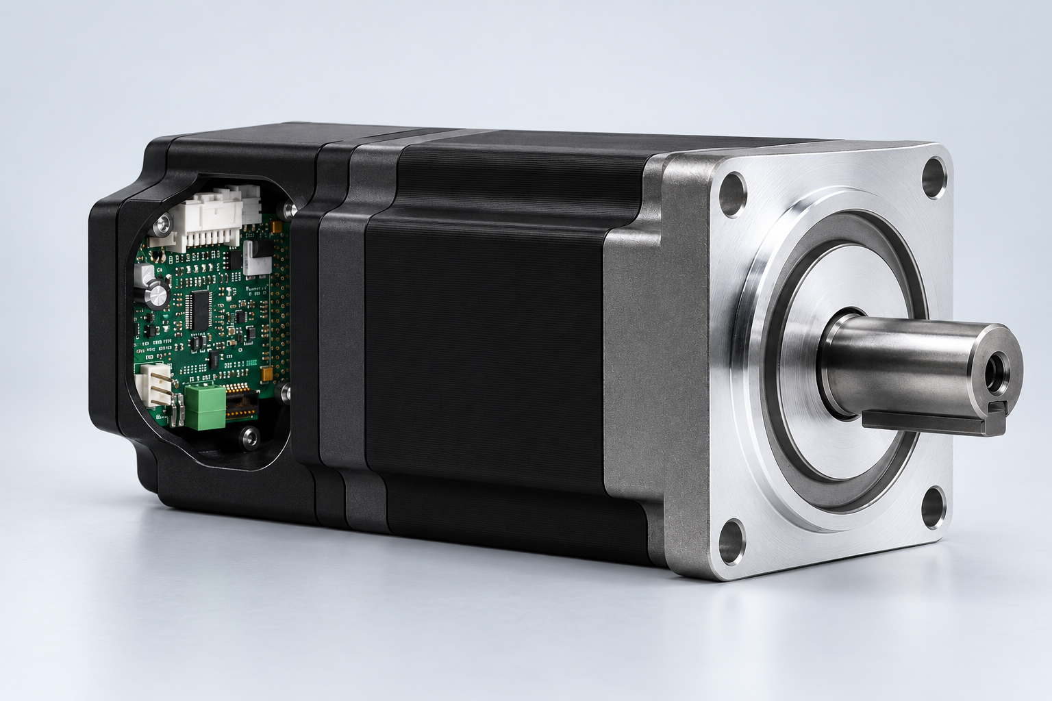
BLDC Motor with Integrated Controller
Motor, commutation electronics, feedback and protection combined within one coordinated package to reduce wiring and installation space.
Explore More →IE1–IE5 motor efficiency
From Standard Efficiency to Ultra-Premium IE5
IE identifies an efficiency class—not one motor construction. SDT supports IE1–IE5 routes by selecting the appropriate line-operated induction, converter-fed synchronous-reluctance or permanent-magnet technology, with EC and brushless alternatives where the application requires them.
SDT IE5 route: the solution may be a classified line-operated motor or a converter-fed SynRM/PMSM package. The applicable standard, motor class, control architecture and supporting test basis are defined for the selected configuration.
Explore MoreClassified motor efficiency
Eligible line-operated motors are classified under IEC 60034-30-1; its 2025 edition introduces IE5 limits for motors within its defined scope.
Ultra-premium technology route
Synchronous-reluctance and permanent-magnet designs remove induction-rotor copper losses and can provide high efficiency across useful operating points.
Matched control architecture
Converter-fed routes use compatible drive control and parameters to achieve the specified speed, torque and efficiency performance.
Complete-system evidence
Motor efficiency and complete power-drive-system efficiency are separate claims; drive-system losses are assessed under IEC 61800-9-2.
Technology-selection guidance
What Determines the Right Technology?
A credible selection begins with the complete application rather than one headline rating.
Control and integration architecture
How the Selected Technology Becomes a Working Drive System
Variable speed, an integrated controller, servo behaviour or direct drive are system decisions built around the selected motor technology and equipment requirement.
Variable-Speed Motor & Drive
VFD-fed induction or SynRM, electronically commutated BLDC/PMSM/EC and controlled PMDC solutions matched to the required operating envelope.
Integrated Motor & Controller
Smart EC and selected brushless, stepper or servo packages combine motor and electronics to reduce wiring, installation space and commissioning effort.
Feedback & Motion Control
Hall sensors, encoders, resolvers, sensorless algorithms and equipment feedback are selected around speed, torque or position behaviour.
Mechanical Drive Architecture
Direct drive, gearbox, brake, shaft, mounting, wheel or transaxle integration is developed with the motor and controller—not added as an afterthought.
From evaluation to production
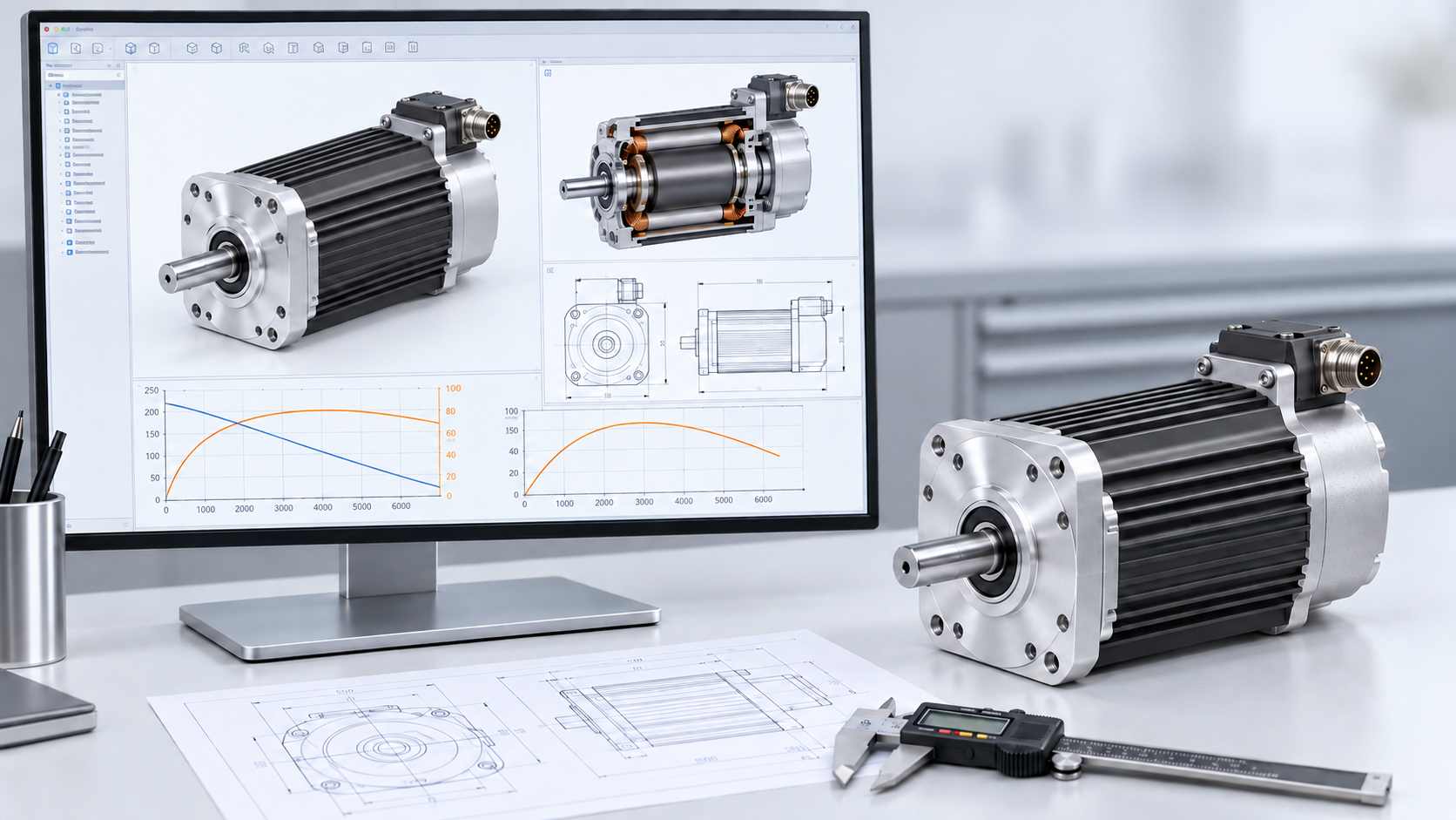
Technology Decisions Supported by Engineering Evidence
SDT’s electric-machine engineers support technology selection with published engineering work, application definition, engineering evaluation, prototype correlation, verification and production readiness. This evidence includes documented contributions to brushless DC, switched-reluctance, high-speed and traction-machine development.
Explore More