
Hybrid Stepper Motors
20–90 mm platforms covering compact positioning through higher-torque industrial duties.
Positioning motors and matched drives
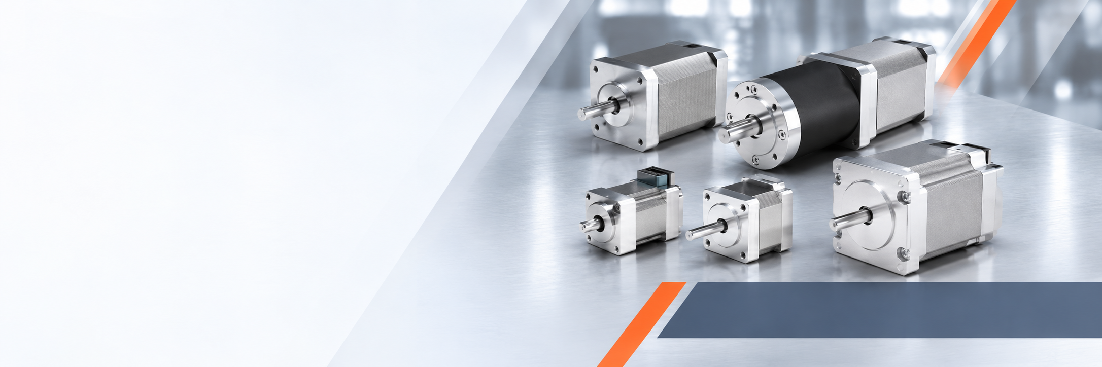
Two-phase hybrid stepper platforms from 20 to 86 mm, supported by matched microstepping drives, feedback, brakes, gearheads and integrated controls.
Product architecture
Select the motor construction, control method and mechanical options around the operating load, speed profile and installation environment.
20–90 mm platforms covering compact positioning through higher-torque industrial duties.
Pulse-and-direction control with supply and current ranges matched to the selected motor.
Motor, controller and encoder packages for improved position confidence and stall detection.
Modified windings, shafts, feedback, brakes, connectors and complete OEM subassemblies.
Representative SDT platform range
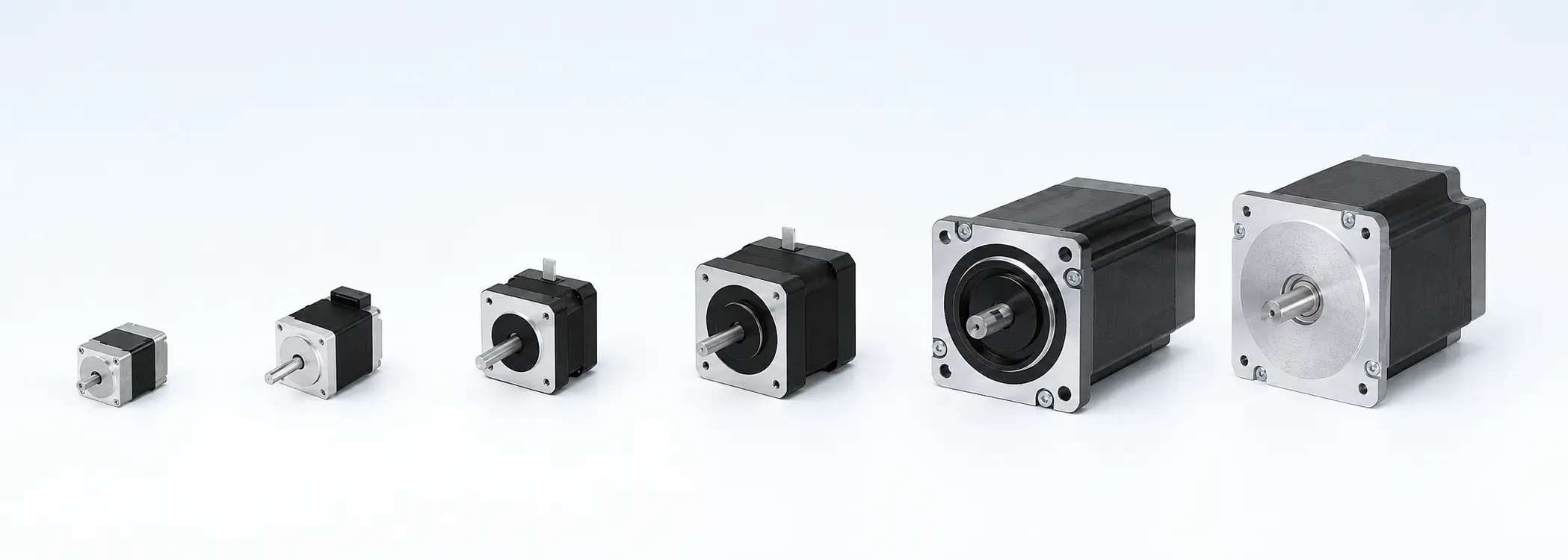
Standard two-phase frame coverage for preliminary selection, progressing from miniature instrumentation to higher-torque industrial motion.
| Series | Approx. NEMA | Frame | Step angle | Typical phase current | Holding torque | Phase resistance | Inductance | Motor length |
|---|---|---|---|---|---|---|---|---|
| SD20 | NEMA 8 | 20 mm | 1.8° | 0.4–0.8 A | 0.03–0.05 N·m | 5–10 Ω | 2–5 mH | 30–45 mm |
| SD34 | NEMA 14 class | 34 mm | 1.8° | 0.8–1.8 A | 0.10–0.35 N·m | 1.5–6 Ω | 2–8 mH | 25–45 mm |
| SD35 | NEMA 14 | 35 mm | 1.8° | 1.0–2.0 A | 0.15–0.40 N·m | 1–5 Ω | 1.5–7 mH | 28–50 mm |
| SD42 | NEMA 17 | 42 mm | 1.8° | 1.0–2.5 A | 0.20–0.80 N·m | 0.9–4.5 Ω | 1.4–8 mH | 33–60 mm |
| SD57 | NEMA 23 | 57 mm | 1.8° | 2.0–5.0 A | 0.6–3.0 N·m | 0.3–2 Ω | 1.5–6 mH | 40–90 mm |
| SD86 | NEMA 34 | 86 mm | 1.8° | 4.0–6.5 A | 4.5–12 N·m | 0.2–1 Ω | 2–8 mH | 75–130 mm |
Selection basis: Holding torque is a static rating. Available running torque falls as speed rises and depends strongly on winding inductance, driver voltage and current, microstepping, acceleration and load inertia. SDT confirms the applicable speed–torque curve and thermal margin before final model selection.
Complementary control
Microstepping control provides smoother low-speed motion and reduced resonance, but the driver must be selected from motor phase current, winding inductance and the required speed–torque curve.
| Motor frame | Recommended supply | Output current capability | Control | Microstepping | Typical use |
|---|---|---|---|---|---|
| 20 mm | 12–36 VDC | 0.3–1.5 A peak | Pulse / Direction | Up to 1/16–1/256 | Compact instruments and light positioning |
| 34 mm | 18–36/40 VDC | 0.5–2.2 A peak | Pulse / Direction | Up to 25,600–51,200 steps/rev | Small automation and instruments |
| 35 mm | 18–40 VDC | 0.5–3.2 A peak | Pulse / Direction | Up to 25,600–51,200 steps/rev | Automation and precision axes |
| 42 mm | 18–50 VDC | 0.5–4.2 A peak | Pulse / Direction | Up to 51,200 steps/rev | General NEMA 17 motion |
| 57 mm | 20–50/80 VDC | 0.5–5.6/7.0 A peak | Pulse / Direction; fieldbus option | Up to 51,200 steps/rev | Industrial NEMA 23 motion |
| 86 mm | 30–110 VDC or 20–80 VAC | 2.4–8.2 A peak | Pulse / Direction; CANopen option | Up to 51,200 steps/rev | High-torque NEMA 34 axes |
Drive selection: The current setting must suit the motor winding. A higher DC-bus voltage, within the motor and driver limits, generally improves torque retention at speed. Command interface, microstep resolution, EMC, braking energy and enclosure cooling are confirmed as part of the machine control system.
Configured for the application
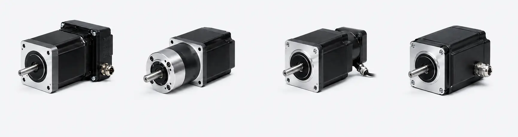
Representative motor arrangements show the available integration routes. Use the guided decisions below to connect each option to the load, motion profile and installation environment.
Industries & applications
Stepper technology is strongest where controlled incremental movement, holding capability and practical system integration matter more than continuous high-speed operation.
Modified or newly developed
Share the moving load, speed and acceleration profile, positioning accuracy, duty cycle, available supply, envelope and environmental conditions. SDT can then select or configure the motor, drive and mechanical interface as one coordinated solution.
Define the appropriate stepper solution
Share the load, travel, speed, accuracy, supply, installation envelope and duty cycle.