Technical Application Notes
Duty Cycle Applications
"Duty" is defined as being the load condition the machine is subject to, including (if applicable) the periods of starting, electrical braking, operating with no load, and rest, as well as their duration and sequence in time.
The duty can be described by one of the types of service indicated below, in conformity with IEC34-1, or by another type identified by the user, possibly with the aid of a graph showing the succession in time of the variables. If the succession in time of the values of the variables is not defined, a fictitious succession will need to be chosen that is equivalent but no less severe than the actual one, in conformity with one of the predefined services. If the service is not stated, service S1 is applied.
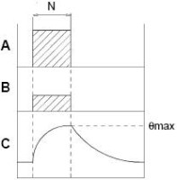
S1 continuous service
.jpg)
A = Load
B = Energy losses
C = Temperature
D = Starting or acceleration time
N = Operating time with constant load
R = Rest time
R I= Intermittency ratio
θmax = Maximum temperature reached during the cycle
Operation with constant load of sufficient duration to reach a thermal balance. The user needs to provide accurate information on the load and nominal conditions of operation the machine needs to operate in for an unlimited period.
S2 service of limited duration
Operation with constant load for a definite period of time, shorter than that required to reach thermal balance, followed by a sufficiently long rest period for the machine temperature to return to ambient temperature, with a tolerance of 2°C.
This service is abbreviated to S2 followed by an indication of the operating time. The user needs to provide accurate information about the load, duration and nominal conditions of operation the machine, started up at ambient temperature, can work in during a limited period.
Example of designation: S2 30 min.
S3 periodical intermittent service
.jpg)
A sequence of identical cycles of operation, each one including a period of operation at constant load and a rest period. In this service the cycle is such that the starting current does not affect the over-temperature significantly.
This service is abbreviated to S3 followed by an indication of the intermittency ratio. The duration of the cycle, on the basis of which them intermittency ratio is calculated, is 10 minutes. The user needs to provide accurate information about the load and nominal conditions of operation the machine can operate in with a periodical cycle.
Motor Temperature and Insulation System
Motor Temperature
A major consideration in both motor drive design and application is heat. Heat has an effect upon electrical resistance, magnetic characteristics, viscosity of lubricants, rate of volatilization of lubricants, dielectric strength of insulation and life of physical components in general. These effects must be taken into consideration in each motor application.
In this respect, the total temperature a motor must withstand is the result of two factors: external, or ambient temperature; and internal, or motor temperature rise. An understanding of how these components are measured and expressed is important for proper motor application. For a given application, the maximum sustained ambient temperature, measured in degrees Celsius, should be determined. Most motors are designed to operate in a maximum ambient temperature of 40°¡C. If the ambient temperature exceeds 40° C, the motor may need to be modified to compensate for the increase in total temperature.
The temperature rise is the result of heat generated by motor losses during operation. At no-load, friction in the bearings, core losses (eddy current and hysteresis losses), and stator I²R losses contribute to temperature rise; at full-load, additional losses which cause heating are rotor I²R losses and stray load losses. ( I = current and R = resistance of the stator or rotor /armature windings).
Since current increases with an increase in motor load and under locked-rotor, temperature rise will be significantly higher under these conditions. Therefore, applications requiring frequent starting and/or frequent overloads may require special motors to compensate for the increase in total temperature.
Insulation Class vs Temperature
Electrical insulation systems are classified according to the maximum temperature that they can withstand. In motors, classified by maximum allowable operating temperature. NEMA classifications include: Class A = 105°C, Class B = 130°C, Class F = 155°C and Class H = 180°C.
The temperature rise of a motor is the difference between the measured temperature of the motor winding and the ambient temperature.
The total temperature is the sum of ambient temperature plus the motor’s temperature rise. The following charts illustrate the maximum total motor temperature allowed for each of the standard classes of insulation. An additional 10 degrees C measured temperature rise is permitted when temperatures are measured by detectors embedded in the winding. . A hot-spot allowance must be made for the difference between the measured temperature of the winding and the actual temperature of the hottest spot within the winding, depending upon the type of motor construction. The sum of the temperature rise, the hot-spot allowance, and the temperature of the ambient must not exceed the temperature rating of the insulation.
Example fror motor either Class A or Class B insulation systems are rated at 105° C and 130° C respectively for the hottest-spot temperature.
The life of the electrical insulation and of the lubricants is adversely affected by high temperatures. A generally accepted "rule of thumb" is that for every 10° C increase in operating temperature, life is halved.
Gearbox Application
Performance
If gear units had no losses, the torque at the output shaft of a gear motor would equal the motor torque multiplied by the reduction of the gear train. Since all gearing does have some internal losses, the actual output torque will be less than the calculated no-loss value by a factor known as gearing efficiency. The efficiency of a gear train will vary with the number of gears. For rough approximation, a value of 7% to 10% loss per gear may be assumed. When precise calculation is necessary for a specific gear reduction, values should be obtained from the factory.
 |
 |
When high gear reductions are used, the torque at the output shaft may exceed the strength of the gearing. For this reason a maximum torque value, a gear torque rating, must be specified to prevent gearing damage. Gear torque ratings are based upon a uniform, steady torque load. Dynamic or shock loads impose stresses which can exceed gearing strength or cause early fatigue failure. To some extent this can be taken into consideration in a reduced gear torque rating. However, dynamic braking with inertial loads or locking of the output shaft can force the gearing to absorb destructive amounts of kinetic energy stored in the momentum of the load or the rotor with immediate or rapid failure. As an example, permanent magnet motors with gear trains should not be stalled since the inherent pulsating nature of the stall torque can cause gearing damage in a short period of time.
Torque rating
The majority of real-world gear applications far exceed 2 x 10⁶ load cycles. For this reason, the recommendation of nearly all gear rating standards - AGMA, ISO, DIN - is to base gearbox torque ratings on endurance limits and minimum bearing life. For industrial gearboxes, AGMA recommends 5,000 to 10,000 hours.
There is only one true rated torque for a gearbox - for continuous duty. Unfortunately for marketing reasons sometimes ill-defined acceleration torques, peak torques, or emergency-stop torques are used as references. Still, only in applications where the number of load cycles is below 2x10⁶ are loads exceeding rated load permissible. The majority of real-world automation applications reach this number of load cycles in a few days, weeks, or in a best-case scenario, after some months of operation. As a rule of thumb
If the peak load cycle is part of the designed standard working duty cycle of the machinery, the peak load should not be higher than the rated torque unless the machinery is only working a very limited time. An hour of operation a day qualifies.
Another situation where peak loads can exceed rated torque is if the user and OEM do not expect extended, maintenance-free life. Since simple RMC calculations are not applicable to other internal gearbox components in such cases, data should be submitted to the manufacturer.